 Nestronics
Nestronics
Nestronics
Last Edit: 2026-03-19
Index
What about the existing marketed PEMF Products?
PEMF Required Specifications
PEMF Reference Design goals
How to create a Uniform Rotary Magnetic Field (Homogeneity)
Rev 03 Reference design: DC/DC converter to control field level (not recommended)
Rev 06 Reference design: PWPWM modulation to control field level
Rev 07 Reference design: Adds ability to change frequency of Burst
Build a Hall Effect Sensor
Prototype test results
Rotary vs Vertical and Horizontal UREBS magnetic field *** Cool Videos of effects on Iron Powder ***
AI generated Field Patterns
There are many PEMF products in the market, but it is hard to tell what they are because they generally list no specifications.
If someone is selling anything with out proper specifications, I would avoid it.
Basically all PEMF devices will take electrical power and convert it to some form of magnetic field.
Any wire with an electrical current thru it produces a magnetic field. When the wire is looped into a coil the magnetic field becomes stronger.
All PEMF devices use that principal and generally speaking there are perhaps 3 types:
a) continuous waveform
b) single pulse, repeated
c) Burst waveform, repeated
The most common specifications listed are:
Magnetic Field Strenght: uT (microTesla) or mT (milliTesla) or sometimes listed in Gauss
Waveform Shapes: Common examples, sine, saw tooth, triangle, square wave, etc.
Frequency: generally in Hertz
They may reference research papers, and use unrecognized claims and even include testimonials.
But a proper product must be defined by it's specifications.
The biggest example of an important specification is the uniformity of the field. For example you may see "full body mats" advertised.
That implies you are getting full body coverage of the magnetic field, which no doubt you are. But at what uniformity?
If you knew the field strenght varied for example 1:10 (0.1 ratio) or 1:100 (0.01 ratio) would you buy it?
When you are prescribed a medicine does your doctor say you can take anything from 1 to 10 pills/day? Definately not. Controlled dosage is important for effectiveness.
The problem with magnetic fields is the field strenght from a single magnet or coil normally drops off rapidly versus distance.
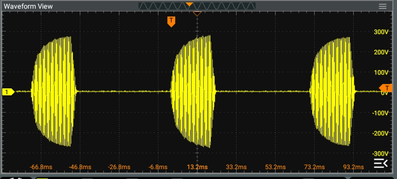
Shown above could be a typical Pulsed ElectroMagnetic Field. This is a visual example of some of the specifications needed.
Here is a list of required specifications to define if a PEMF treatment may be effective.
a. Magnetic Field intensity -in milliTesla (mT) or Gauss (G)
b. Frequency of burst in Hertz (Hz)
c. Repetition frequency/rate of burst in Hertz (Hz) and Pulse ON and OFF times.
d. RATE OF CHANGE of magnetic field in Tesla/second. (T/s)
e. Direction(s) of Magnetic Field, (unipolar, bipolar, horizontal, vertical, rotary).
f. UNIFORMITY of Magnetic Field vs distance (expressed as ratio, where 1=perfectly uniform)
Details on Magnetic Field Intensity Selection
The two categories of ICNIRP recommended limits of interest to us is the "Workplace Exposure", and "Intentional Informed Knowledge Exposure".
We know the ICNIRP workplace recommended limit is 1mTrms. ICNIRP also gives further guidelines for
pulsed exposure:
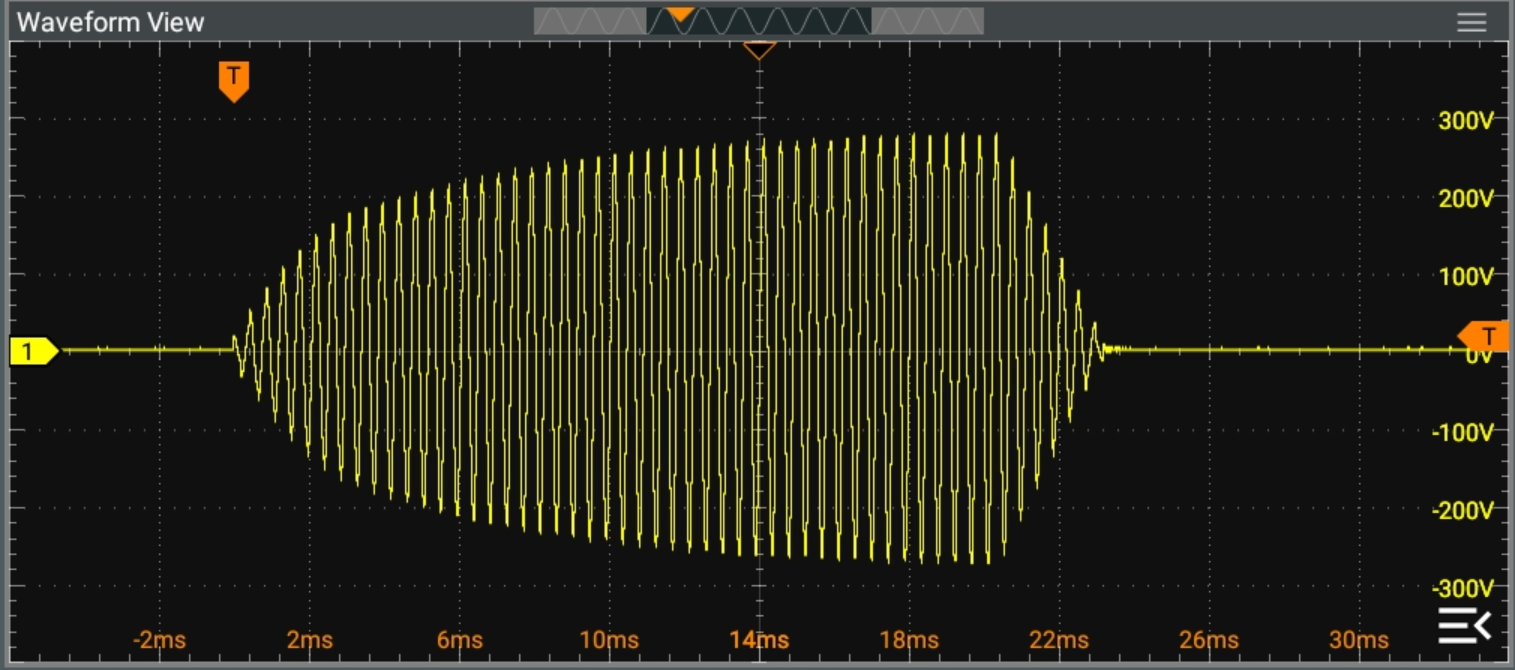
"One type of waveform is the narrow-band sinusoidal
burst, Fig. 2a. This consists of a series of pulses, each
containing at least five or more coherent cycles of
sinusoidal oscillations with very little distortion (i.e., no
higher order frequency harmonics). This waveform has a
peak value that may greatly exceed the root-mean-square
(rms) value depending on the duty cycle which is the
ratio of the “on” time to the pulse repetition period.
Typical examples of sources of sinusoidal-burst fields
below 100 kHz are some anti-theft devices. The ICNIRP
guidelines can be applied for exposures to phase-
coherent sinusoidal bursts by simply restricting the peak
amplitude below a value obtained by multiplying the rms
reference value valid at the carrier frequency by SQRT of 2 ".
This for a 265Hz signal this would mean 1mT rms * 1.414 = 1.414mT peak (Workplace Exposure recommended limit with x10 safety factor)
Althou we can use the Workplace Exposure recommended limits as a guide, a PEMF device is for intended exposure,
and hence we are operating in "Intentional Informed Knowledge Exposure" range, which limits are not defined by ICNIRP.
Presented here is a reference design for the best possible PEMF device for research purposes. We will call this device a Urebs (Uniform Rotary Exciter Burst Sine)
Start with defining the Specification for such a device:
1. Burst Sine Wave approach, meaning periodic application of magnetic field.
Reason:
- for research purposes sine waves are well defined with no harmonics changing the rise and fall times.
Sine waves are replicable with precision, and fully defined with specification of only the amplitude and frequency.
- many research papers use a burst approach including the historic Bassett non-union bone fractures device(non sine wave),
and the more recent OncoMagnetic device(sine wave), by Houston Methodist Hospital.
- burst approach matches ICNIRP recommendation for magnetic field exposure limits, that states that no time averaging is allowed in exposure limits.
Meaning that a burst could have the same impact as a continuous sine wave for work place exposure.
2.Adjustable burst frequency and level (which together define T/s), and burst time duration and spacing.
Reason:
- to allow repetition of published results.
- adjustable burst time and spacing helps ensure no heating effects.
- adjustable burst time and spacing helps acheive practical power limitations.
- adjustable burst frequency and level to stay within guidelines of exposure limits of T/s.
Design Target:
Frequency: 265Hz
Level: 1mT rms / 1.4mT peak (min desireable)
Tesla/sec: 1.6T/s (computed from 2 * pi * 265Hz * 1.4mTp = 2.3T/s)
(justification is ICNIRP is 2.7T/s for workplace exposure)
3. Burst ON/OFF time duration
- Burst on Time: 40ms (some what arbritary picked becuase adjustable)
- Burst OFF Time: 450ms (some what arbritary picked becuase adjustable)
Overall this results in about a 2Hz Burst repetition frequency.
4. Uniformity (Homogeneity) of magnetic field over range of depth of application.
We will define the objective depth of 30cm to match the approximate depth of the human body when laying down.
Uniformity is defined as a ratio with respect to 1 being the strongest exposure.
For example the OncoMagnetic device varies from 58.3mT@1.4cm to 0.7mT@7cm.
So over a 5.6cm range the uniformity ratio is 0.7/58.3=0.012.
An ideal device would have a uniformity ratio of 1.
Design Target: 0.5 uniformity ratio for 30cm. (meaning over a 30cm distance, the field could vary from 1mT to 0.5mT peak.
5. Type of magnetic field: Rotary (taking advantage of some research papers claiming rotary is superior to directional).
With optional settings for Vertical only field, or Horizontal only field.
One option is to simply rotate a magnet on an axis. The problem with this approach is some pretty huge physical limitations.
To get to a frequency of 265Hz, means a rotation speed of 265 x 60 = 15,900 rotations per minute (RPM), with huge acceleration requirements to support burst operation.
That is very challenging, and only possible with small magnets. The smaller the magnet the more nonuniform the magnet field pattern vs distance.
The solution is to produce the field from electromagnets (coils). However it takes 2 interacting magnetic fields (90 deg apart) to produce a rotating magnetic field.
The classical way to implement a rotating field (for research) is to use 2 pair of Helmholtz coils.
One pair in the X plane, and one pair in the Y plane. Each pair of coils is driven 90 degrees out of phase.
Note that creates a box shape, resulting in problems for human body access.
Here an alternative approach is used, to improve human body access. The rotating field is produced from 2 planes only, instead of 4.
The unique advantage of the 2 plane approach is the magnetic field drop off rate is the same for both the horizontal and vertical fields.
This keeps the rotary magnetic field symmetrical versus distance.
The below coil pairs shows a prototype with a spacing of about 16" (41cm). This distance permits reasonable human body access.
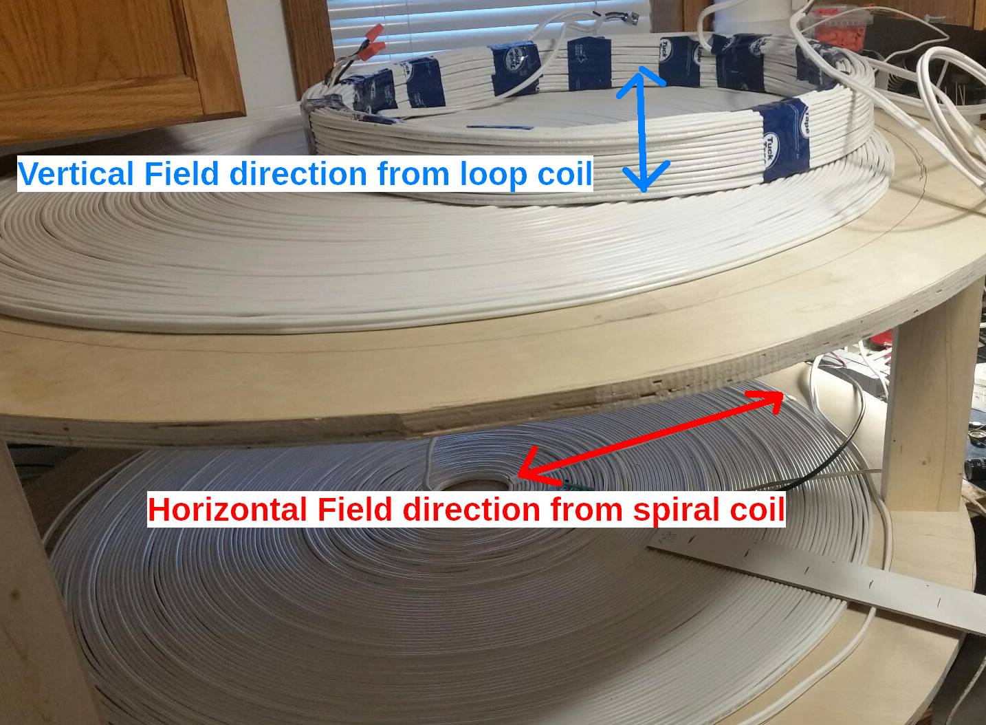
The loop coil pair (2nd one is under the lower spiral coil) generate a vertical magnetic field. The Spiral coil pair generate a horizontal magnetic field.
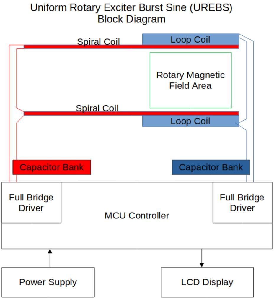
The above block diagram shows how the coils are driven from the Controller.
Resonance is used to generate the magnetic field, as this is the most efficient method and can provide the greatest level.
The resonance is set up between the total inductance of each series pair, and the corresponding capacitors, using the standard LC resonance equation.
f = 1 / (2π √L C) (Alternately online LC resonance calculators are available.)
It is also necessary that the controller drive the full bridge at the resonant frequency. Typical full bridge driver voltages are 10 to 30V.
However due to the resonance the voltage across the inductors (coils) and capacitors rises to up to 200Vrms or higher.
The driver voltages need to be individually adjustable to allow for adjustment of magnetic field strenght.
The prototype above uses readily available 14/2 electrical wiring. Each wire has 3 conductors each of 14ga.
All 3 wires are connected in parellal to lower the resistance. Some coils have greater than 150m of wire meaning the resistance is about:
14ga wire: 8.3 milliOhm/meter
0.0083 x 150m / 3conductors = 0.42 ohms
Since 2 coils are placed in series the total resistance for a coil pair is about 1 ohm.
At a frequency of 265Hz there is basically no increase in resistance due to the skin effect.
Rev 03 reference design is an preliminary version using DC/DC converter to control the level of the magnetic field.
Here is the full documentation on how to build Rev 03/04 .
Rev 03 is now archived, and it is recommended to use Revision 07 or higher as a reference design.
Rev 07 reference design is a version using PSPWM (Phase Shift Pulse Width Modulation) to control the level of the magnetic field.
Here is the full documentation on how to build Rev 06 .
Rev 07 reference design builds on the PSPWM design of Rev 06 but optionally adds the ability to change the frequency of the burst,
by adding 2 relay boards to switch in/out capacitors in the resonant circuit.
It allows the frequency to be selected from 210Hz to 265Hz in 5Hz steps.
Here is the full documentation on how to build Rev 07 .
Build a Hall effect Sensor to measure Magnetic Field Strenght
We are going to use an oscilloscope to measure the magnetic field, as then we can view the strength and the phase.
There are 3 common ways to express the level of an alternating field, RMS (Root Mean Square), Peak, or Peak to Peak.
We are going to go with the RMS method on the oscilloscope as it provides for more accurate measurements than a Peak measure.
(Peak measurements are more sensitive to noise). To convert to peak (for a sine wave) just multiply by 1.414.
The Allegro Microsystems ACS70311LKTATN-010B5-C Hall effect sensor
provides for an output of 10mV/G (100mVp/mTp), and a bandwidth of 250KHz. Technically this specification cooresponds to peak values.
However it would be equally valid (for sine wave) to convert the voltage reference to RMS and state 70.7mVrms/1mTp.
We use an op-amp with a gain of 14.14 to convert the 70.7mV RMS to 1V RMS.
That way for each 1V RMS measured on scope would coorespond to 1mT peak.
An edge mount "F" or BNC connector is used to allow the use of a sheild cable directly to the oscilloscope.
A separate wire pair is run for the power.
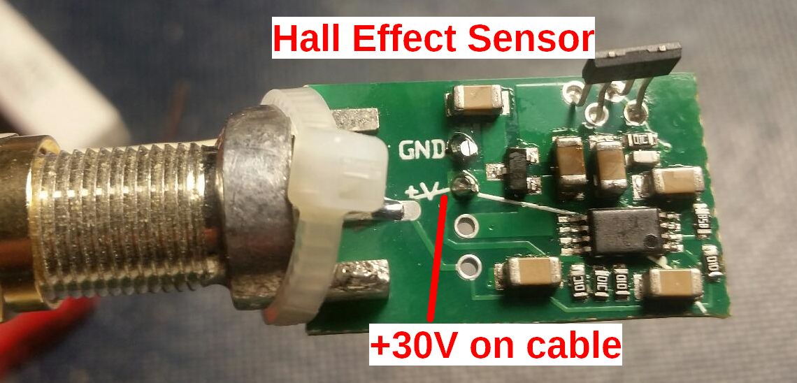
For convenience we make the sensor powered from the same single voltage supply (30V) available on a connector on UREBS.
Link to the Schemeit Schematic for the Hall Effect Sensor
Here is a short Video of the rotating phase as a hall effect sensor is manually rotated 180 degrees.
The blue trace is the output from the hall effect sensor amplifier. The Yellow and Purble traces are the 90 degree driving waveforms.
Test Results: Field Strenght
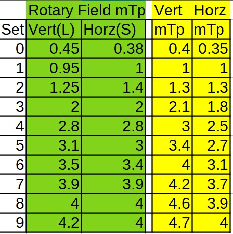
The UREBS is capable of Rotary, Vertical, or Horizontal Magnetic Fields, adjustable in 10 steps from 0.4mTpeak to 4mTpeak.
Burst time is 40ms, and the repetion rate of the burst is adjustble from 4 per second(4 Hz), to 1 per 2 seconds (0.5Hz)
However settings above about 3mT may exceed the specifications of the MOSFETs and reduce their lifespan.
As an design for research purposes this is acceptable.
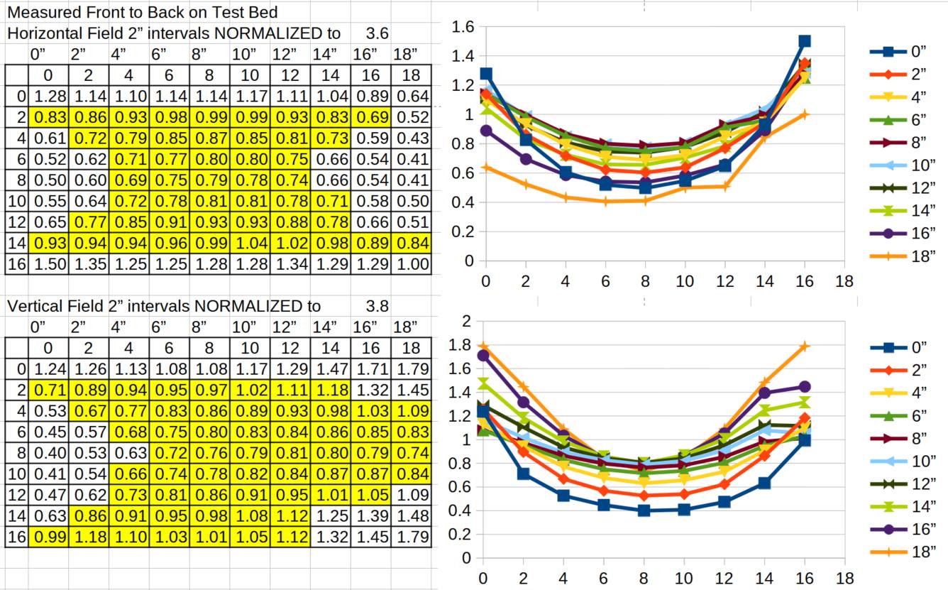
Test Results: Field Uniformity
The uniformity of the magnetic field vs distance is perhaps the most important measurement.
As shown below there is a noticable concave effect to the magnetic field.
This is because the distance used exceeds the distances used in a helmholtz configuration, as we don't need a perfect uniformity. Our goal of 0.5 was deemed acceptable.
Assuming allowance for some practical limitation such as use of a thin 2" mattress for comfort, and upper clearance, the goal is acheive.
If you reduce the treatment area from 18" horizontally to 14" a uniformity ratio of 0.7 is acheived.
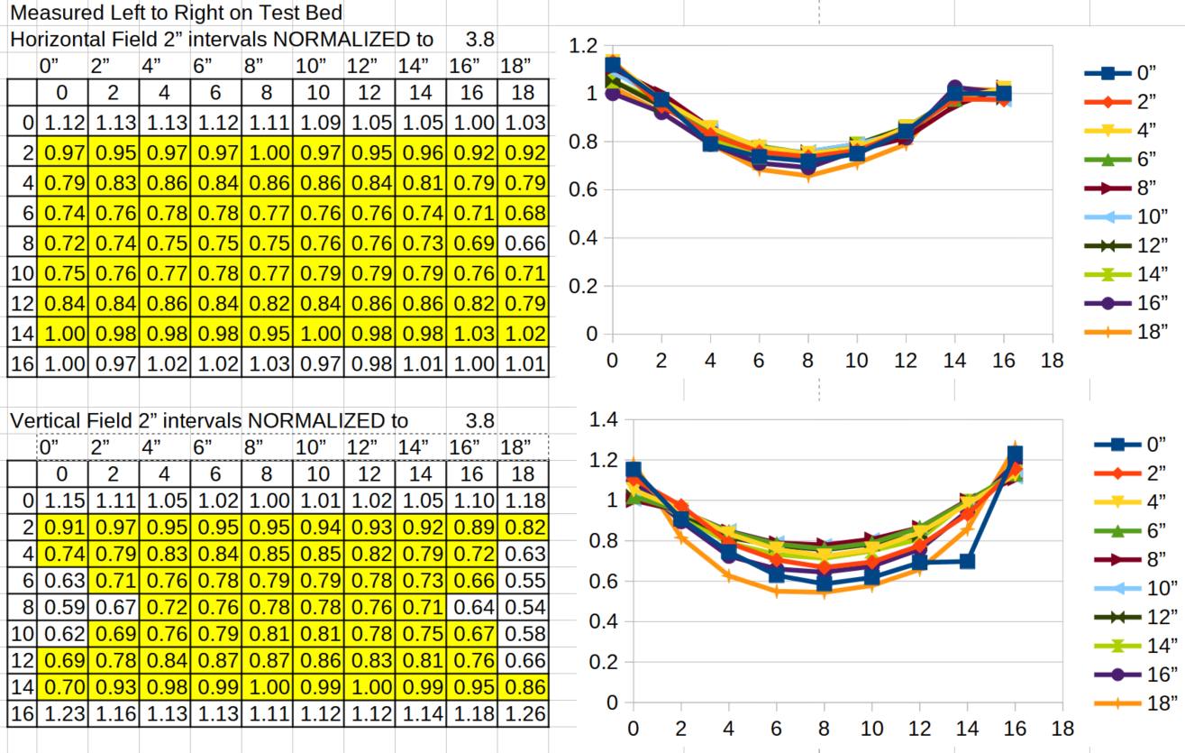
Next is the field uniformity in the front to back direction on the test bed. This direction is worse due to it being the spiral coil narrow direction.
So we need to restrict the treatment width to about 10" to acheive similar uniformity. So that results in an oval shaped reasonably uniform area of about 14" by 10" with a height of about 12".
Total cubic inches is 110"(oval) x 12"height = 1310 sq in.
This compared to a device such as the OncoMagnetic device which uses a small permanent magnet, the target area (for uniformity) likely has to be under one square in.
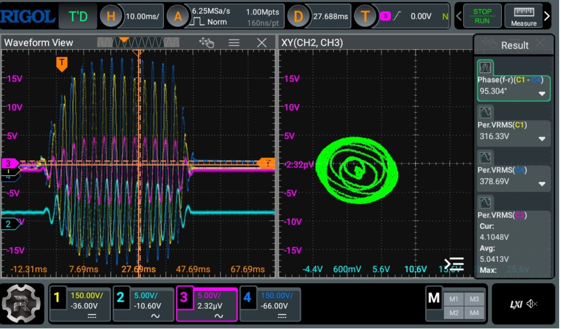
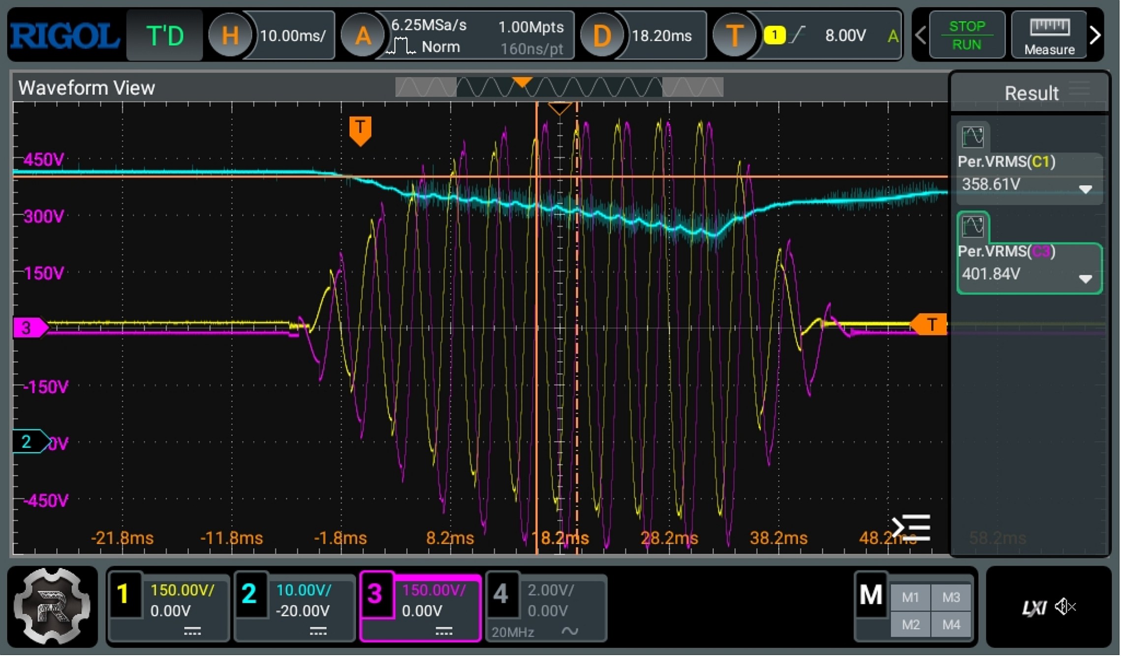
The below scope view is of the highest setting of 9(previous version), which produces a field of 4mTpeak(As of 2024-Sept this is now 5mT peak).
Note the resonant voltage goes to 400V RMS, requiring pulse capacitors rated 600V rms.
Great caution is required at these voltages as it is possible for the voltage to jump through some wire insulation.
(Resulting in possible death)
Also the cyan trace shows the DC/DC converter voltage is not able to keep up, which is why the limit is 4mT peak.
The circuit takes a very high pulse current, so to drive the circuit, it is required to use a 55V (as of 2024 Sept) power supply rated at 5A with proper current limiting.
Proper current limiting means not a hiccup mode type of recovery. This usually means a power supply with an adjustable current limit capability.
Then to handle the pulse current the power supply drives eight 22,000 uF/63V electrolytic capacitors.
When the pulse is generated by the UREBS it takes the necessary pulse current from the capacitors while the power supply goes into current limiting.
Depending on the power setting of the UREBS this could result in up to a 5V voltage drop as the capacitors are discharged.
The capacitors are fully recharged (to 55V) during the off time between bursts.
Rotary vs Vertical vs Horizontal UREBS magnetic field
The UREBS Magnetic Field Exciter, is capable of being switched from a Rotary Field to Horizontal, or Vertical.
It is also capable of alternating the fields during treatment.
It is unknown if alternating field directions has any additional therapeutic effect.
The only reference I could find is the testing of the OncoMagnetic Device.
"We positioned three oncoscillators (3DSeq, Fig. 3A) at right angles to each other and activated them in repeating sequential or alternating cycles compared
to intermittent stimulation with a single oncoscillator (1DSp).
This experiment showed a greater increase in ROS at 2 h in both GBM and DIPG cells with 3DSeq compared to 1DSp stimulation;
however, this difference was not statistically significant (Fig. 3B, C).
The significant increases in ROS levels over control seen at 4 h and 2 h post-stimulation are also not significantly different between 3DSeq and 1DSp (Fig. 3B, C).
This suggests that 1DSp stimulation might be sufficient to produce maximal ROS enhancement given that one activated oncoscillator
sweeps through all angles in a two-dimensional plane."
Below are seperate videos of the different pulsed magnetic Field Effects on Iron Powder.
Rotary Setting: Causes movement away from camera as the Iron Powder "jumps" and rolls away.
Notice also how the Iron Powder has formed vertical towers(flux lines) as well as horizontal flux lines.
Horizontal Setting: forms flux lines, can see some Iron powder "jump" slightly to realign with flux lines
Vertical Setting: All the Iron Powder "jumps" but stays in position.
Alternating Fields Setting:Alternates Rotary, Vertical, Rotary, Horizontal Fields
Added 2024-09-23: Rotating Field Opposite Direction Setting:Rotary Reverse, 4.5mT peak (5mTp not acheiveable in reverse direction)
Note: Paper folded at bottom of video to stop/collect the Iron Powder
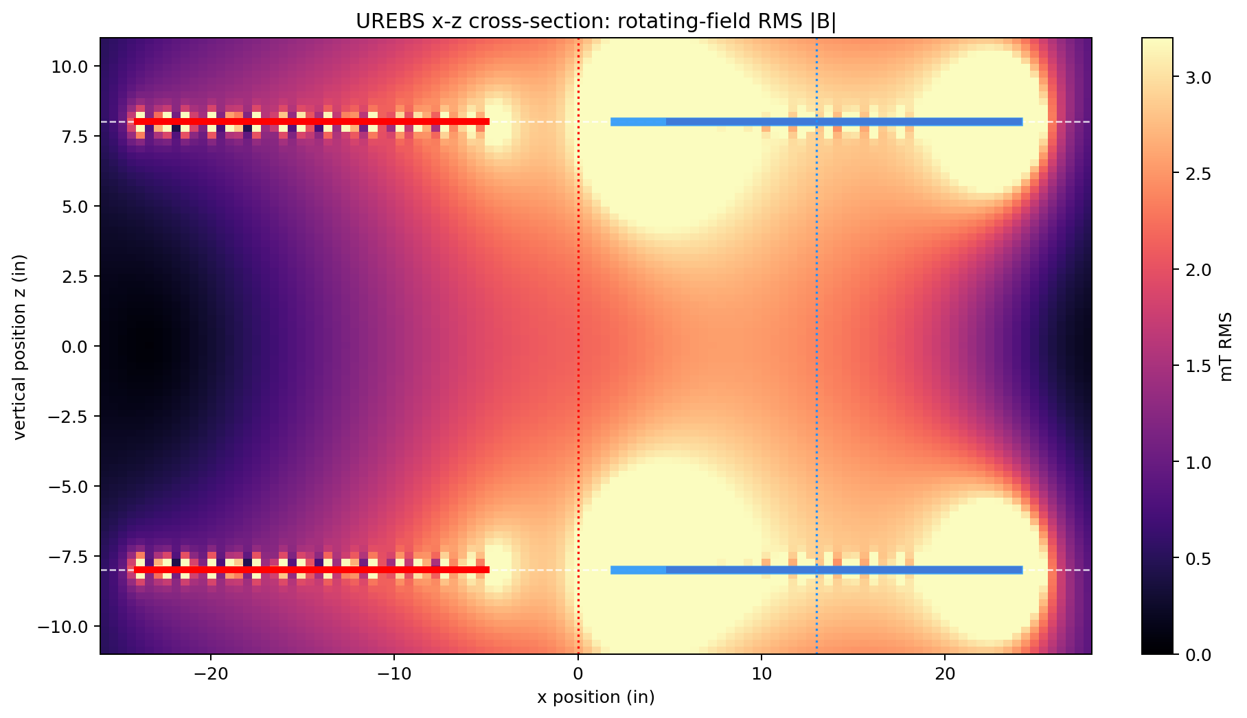
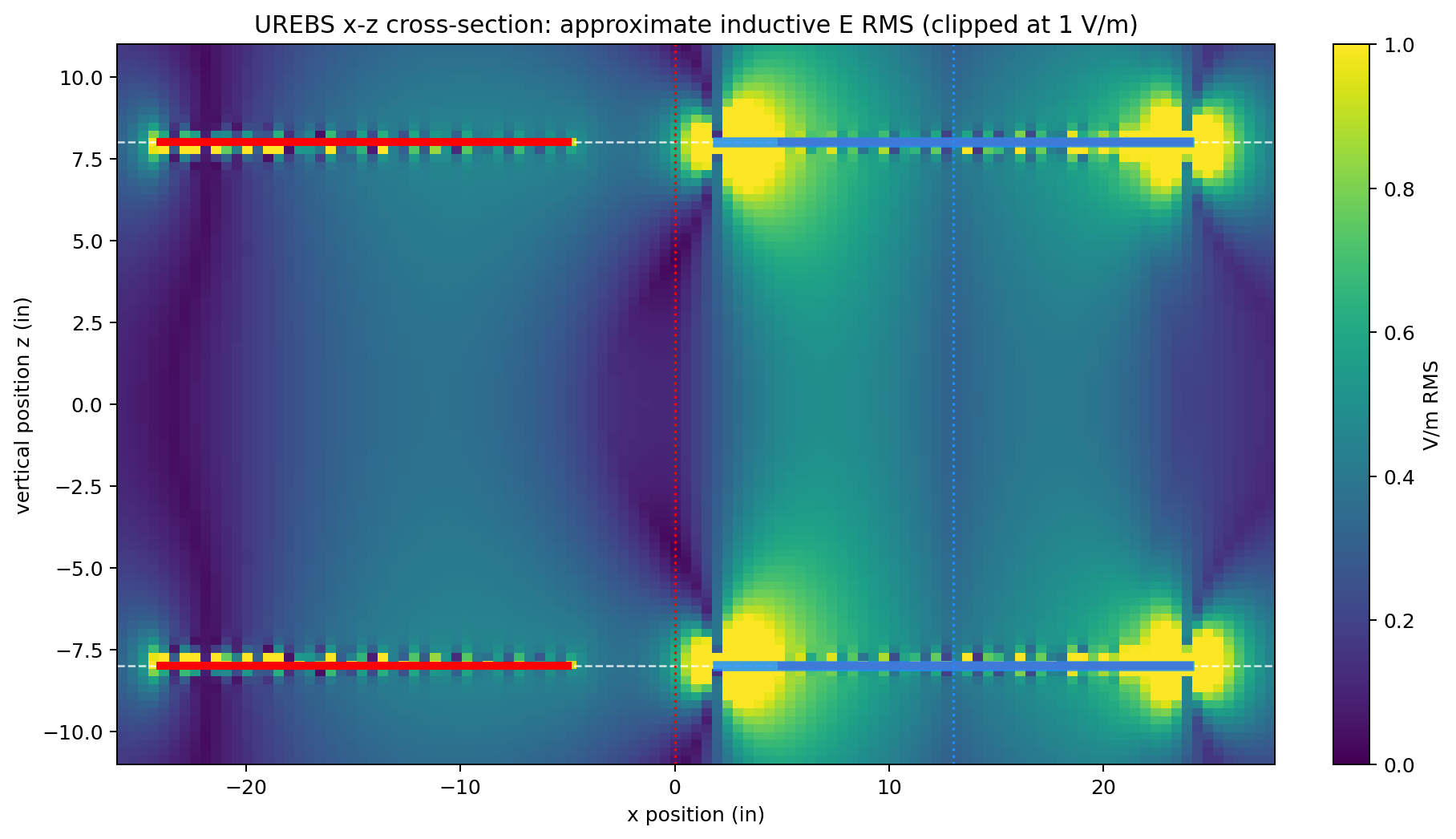
2026-03-18 adding the AI generated field pattern analysis. The key take away here is the B-Field maximun and
the induced E-Field maximuns do not necessary align. So for example placing a test sample in the middle of
the loop coil will be exposing it to a lower E-Field than an offset placement. The induced E-Field increases
linearly from the center axis to the outside edge (ideally)
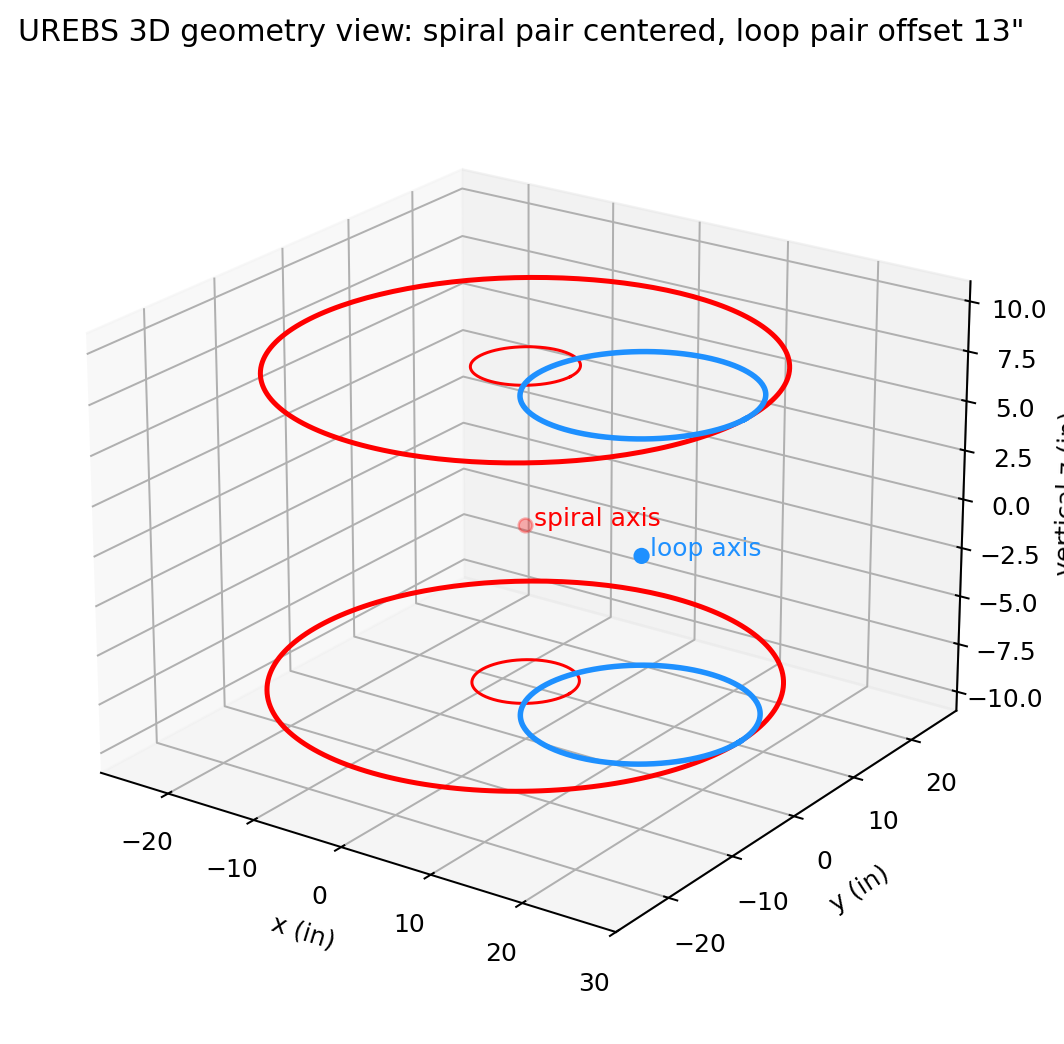
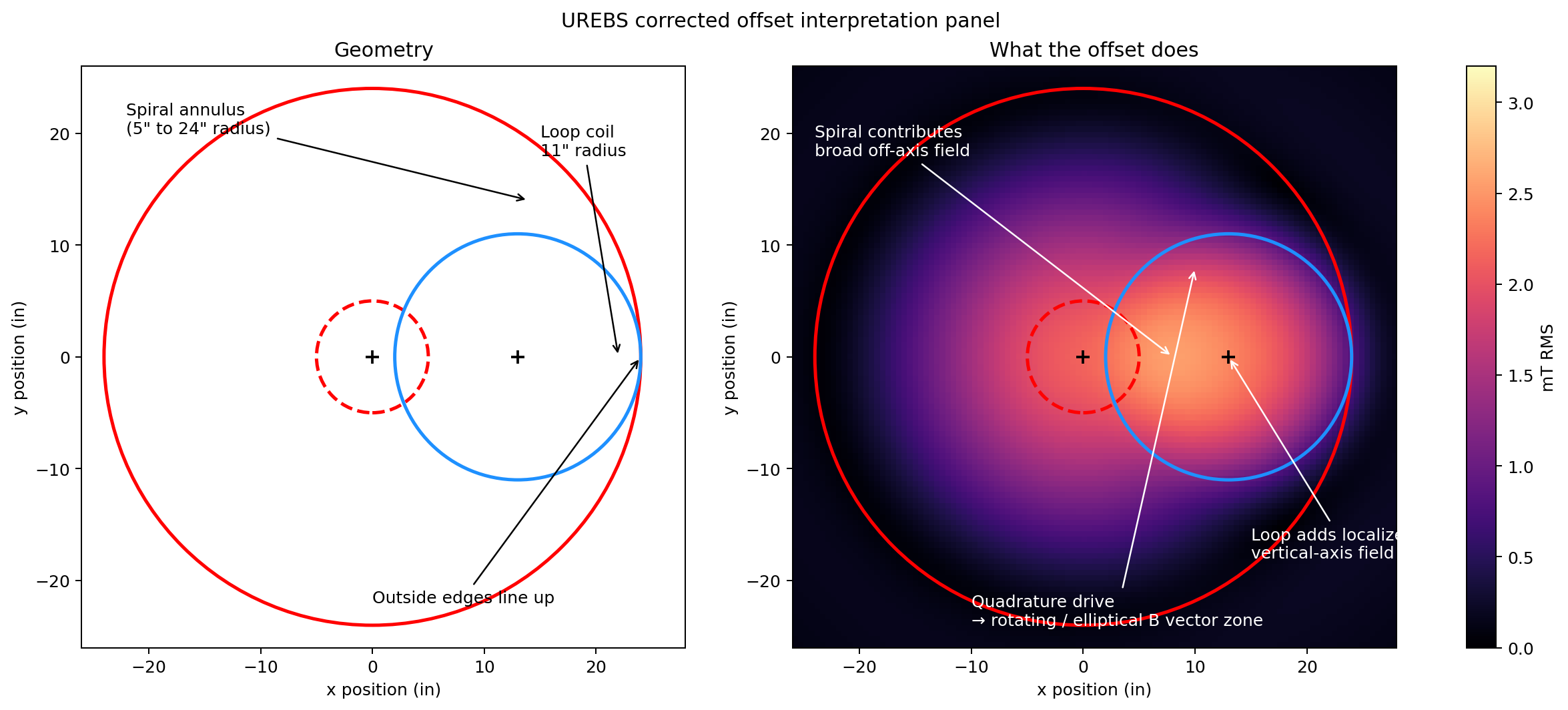
In the follwing 2 images you can see the concave nature of the field strenght, but it mostly only varies from 2-3mT which is not
too bad compared to how fast a field drops from a dipole magnet.
This reduced linearity is a compromise for greater distance between the coils (ie larger field area).
The E field is shaped by:
-where dB/dt is strongest
-where the loop and spiral fields overlap
-distance from the effective magnetic axes
-edge effects near the actual conductor pack
XY plot: The X and Y sources are from 2 Hall effect sensors positioned 90deg wrt each other.
Note that you can also see the rise and fall responce in the plot.
This is a very effective way to visualize the rotating magnetic field.
It also can be useful in calibrating the Horizontal and Vertical field levels to ensure the plot is round.